Gl Tube Type Oil Cooler Series
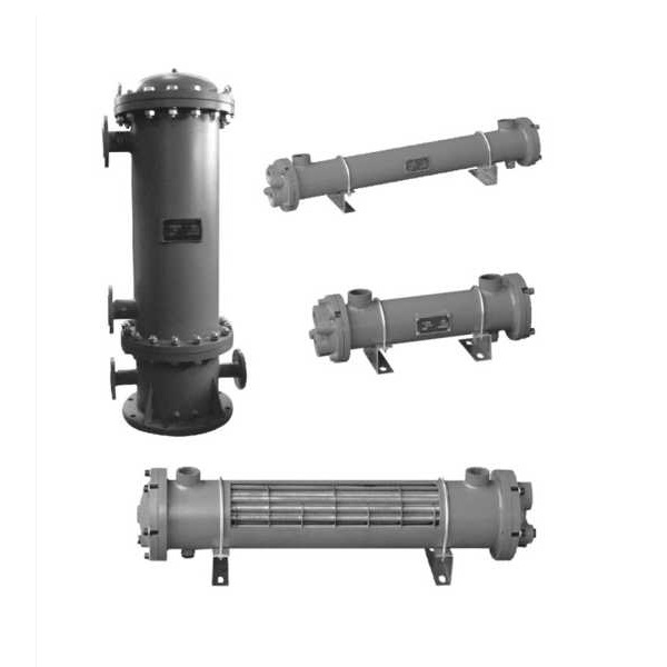
This product is manufactured by our company that combining with the int ernal and external base of advanced technology and craft. The material of h- eat-exchange pipe, adopted low-rib finned red copper pipe, used the structure of transverse current breaker board, turbulence board and the advanced manufacture craft of mechanism expanding, has the features of novel structure, small dimension, light weightand well heat-exchanging effect a- nd soon. This product is a new type and higli efficiency cooler, mainly used in low-viscosity hydraulic and oil system to cool the work oil to the specified temperature. So it is an Ideal cooling facility that can be widely used in cooling the hydraulic equipment in the trade such as chemical industry, electric power, metallurgical industry, mine and light industry and soon.
Each cooler series has many specification and type to suit for each user's requirement. Except the main products introduced in the operation manual, the company also can make all kinds large orspecialcoolerfor the customers according to their requirements.
Tube type oil cooler
C:finned tube
L:bare pipe
Series No.
Nominal cooling area:m2
Special Products :B: Stainless Steel Shell
H: For cooling water is seawater
Inlet and outlet of oil (water) size is different, please directly mark
Other requirements FB- port
Standard can be omitted
Install method:L-vertical; non-horizontal type
Nominal pressure:A = 1.6MPa(omit)
TECHICAL DATA
| Medium viscosity | Inlet-oil temperature | Inlet-water temperature | Oil cooling | Pressure lose | Flow-ratio of oil to water | W/M2 - °C
Heat-exchange factor |
|
|
Oil side |
Water side | ||||||
| N68 | 55 ±1 | W30 | N8 | W0.1 | <0.05 | 1:1 | N350 |
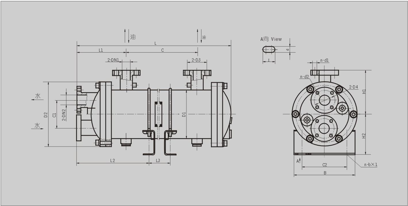
MOUNTING SIZE
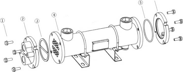
| Number | Name | Note |
| 1 | Bolt | |
| 2 | Cap | |
| 3 | Seal | Wearing parts |
| 4 | Housing | |
| 5 | O-ring | Wearing parts |
| 6 | Cap |
|
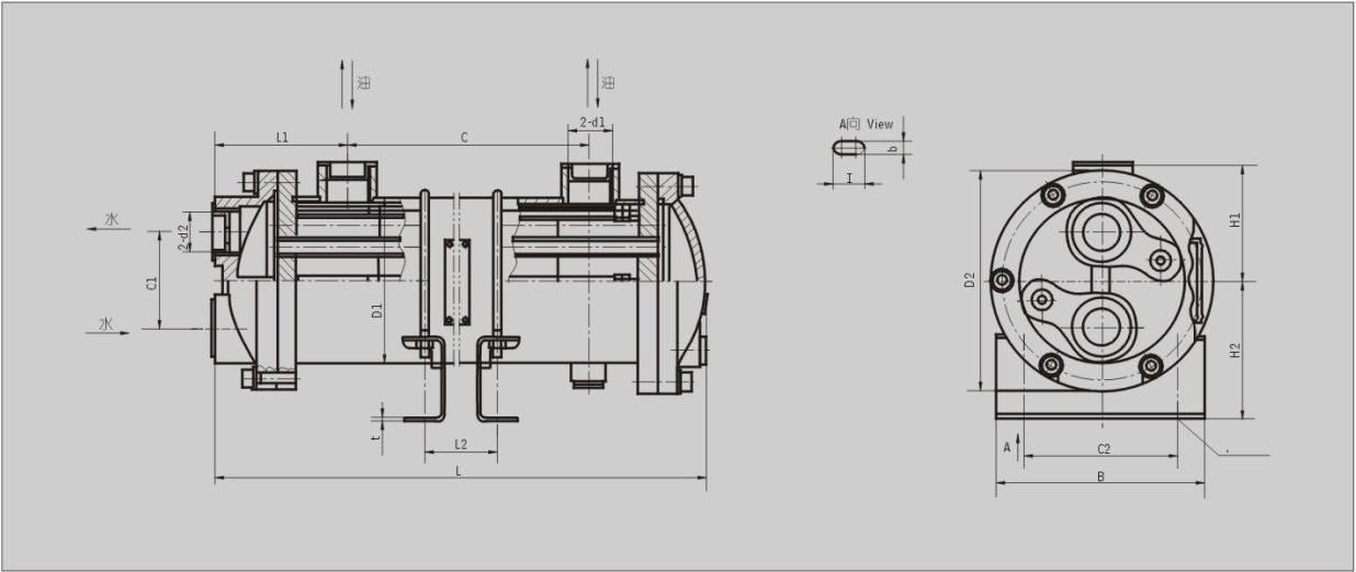
Model |
L |
C |
L1 |
Hl |
H2 |
DI |
D2 |
Cl |
C2 |
B |
L2 |
t |
n-b x I |
dl |
d2 |
Oil flow L/min |
Weight (Kg) |
| GLC1-0.4 | 390 | 240 | 145 |
20 |
7 |
||||||||||||
| GLC1-0.6 | 555 | 405 | 310 |
30 |
9 |
||||||||||||
| GLC1-0.8 | 685 | 532 |
80 |
64 |
75 |
80 |
120 |
50 |
65 |
105 |
435 |
2 | 4-10 x 20 | G1 |
G3/4 |
40 |
10 |
| GLC1-1 | 815 | 665 | 570 |
45 |
12 |
||||||||||||
| GLC1-1.2 | 955 | 805 | 715 |
50 |
14 |
||||||||||||
| GLC2-1.3 | 555 | 375 | 225 |
52 |
17 |
||||||||||||
| GLC2-1.7 | 680 | 500 | 350 |
57 |
20 |
||||||||||||
| GLC2-2.1 | 815 | 635 |
485 |
62 |
24 |
||||||||||||
|
94 |
85 |
100 |
121 | 160 |
70 |
110 |
150 |
2 | 4-10 x 20 | G1 | G1 | ||||||
| GLC2-2.6 | 955 | 775 | 630 |
70 |
28 |
||||||||||||
| GLC2-3 | 1105 | 925 | 780 |
80 |
33 |
||||||||||||
| GLC2-3.5 | 1265 | 1085 | 935 | 85 | 37 | ||||||||||||
| GLC3-4 | 820 | 570 | 380 |
75 |
45 |
||||||||||||
| GLC3-5 | 970 | 720 | 530 | Gll/2 |
Gll/4 |
100 |
51 |
||||||||||
| GLC3-6 | 1120 | 870 | 680 | 125 |
57 |
||||||||||||
| GLC3-7 | 1290 | 1040 | 850 | 150 |
64 |
||||||||||||
|
132 |
115 |
151 |
162 | 220 |
100 |
160 |
205 |
3 | 4-15 x 25 | ||||||||
| GLC3-8 | 1450 | 1200 |
1010 |
175 |
70 |
||||||||||||
| GLC3-9 | 1610 | 1360 | 1170 | 200 |
76 |
||||||||||||
| GLC3-10 | 1780 | 1530 | 1340 | G2 |
Gll/2 |
225 |
83 |
||||||||||
| GLC3-11 | 1960 | 1710 |
1520 |
250 |
90 |
||||||||||||
| GLC4-13 | 1355 | 985 | 745 | 230 |
132 |
||||||||||||
| GLC4-15 | 1515 | 1145 | 905 | 260 |
142 |
||||||||||||
| GLC4-17 | 1675 | 1305 | 1065 | 300 |
153 |
||||||||||||
| GLC4-19 | 1845 | 1475 | 1235 | 330 |
165 |
||||||||||||
|
197 |
160 |
180 |
219 | 310 |
120 |
200 |
280 |
8.5 |
4-22 x 30 | G2 | G2 | ||||||
| GLC4-21 | 2025 | 1655 | 1415 | 360 |
177 |
||||||||||||
| GLC4-23 | 2195 | 1825 | 1585 | 400 |
188 |
||||||||||||
| GLC4-25 | 2375 | 2005 | 1765 | 430 |
200 |
||||||||||||
| GLC4-27 | 2545 | 2175 | 1935 | 470 |
212 |
TECHICAL DATA
|
Medium viscosity |
Inlet-oil temperature |
Inlet-water temperature |
Oil cooling |
Pressure lose |
Flow-ratio of oil to water |
W/M2 - °C Heat-exchange factor |
|
|
Oil side |
Waterside |
||||||
|
N68 |
50 ±1 |
W30 |
N8 |
W0.1 |
<0.05 |
1:1.5 |
N230 |
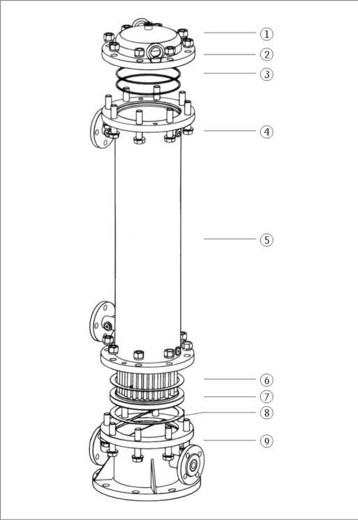
MOUNTING SIZE
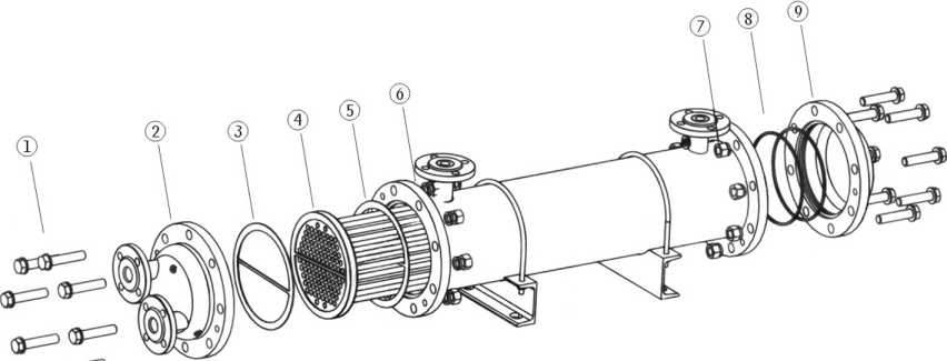
|
Number |
Name |
Note |
| 1 | Bolt | |
| 2 | Cap | |
| 3 | Seal | Wearing parts |
|
4 |
Heat exchange parts | |
| 5 | Seal | Wearing parts |
| 6 | housing | |
| 7 | Nut | |
| 8 | Seal | Wearing parts |
| 9 | Cap |
| Model | L |
C |
L1 |
Hl |
H2 | DI | D2 | Cl | C2 | B |
L2 |
L3 |
D3 |
D4 |
n-dl |
n-d2 |
n-b x I | DN1 | DN2 |
Flow of oil (L/min) |
Weight (Kg) |
| GLL3-4
GLL3-5 GLL3-6 GLL3-7 |
1150
1450 1750 1980 |
682
982 1282 1512 |
265 | 190 | 180 | 219 | 310 | 140 | 200 | 280 | 367 | 485 | 100 |
100 |
4-Φ17.5 | 4- Φ17.5 | 4-22 x 30 |
32 |
32 |
75 100 125 150 |
108 123 138 150 |
| 785 | |||||||||||||||||||||
|
1085 |
110 |
40 |
|||||||||||||||||||
|
1385 |
|||||||||||||||||||||
| GLL4-12
GLL4-16 GLL4-20 GLL4-24 GLL4-28 |
1555
1960 2370 2770 3180 |
960
1365 1775 2175 2585 |
345 | 262 | 232 | 325 | 435 | 200 | 300 | 370 | 497 |
660 |
145 | 145 | 4-Φ17.5 | 4-Φ17.5 | 4-22 x 30 |
65 |
65 |
250
350 450 550 650 |
238 300 360 455 536 |
|
1065 |
|||||||||||||||||||||
|
1475 |
|||||||||||||||||||||
|
1885 |
160 | 8-Φ17.5 |
80 |
||||||||||||||||||
|
2295 |
|||||||||||||||||||||
| GLL5-35
GLL5-40 GLL5-45 GLL5-50 GLL5-60 |
2480
2750 2990 3260 3800 |
1692
1962 2202 2472 3012 |
500 | 315 | 293 | 426 | 535 | 235 | 400 | 500 | 730 |
1232 1502 1772 |
180 | 180 | 8-Φ17.5 | 8-Φ17.5 | 4-22 x 30 |
100 |
100 | 625
750 875 1000 1250 |
570 640 745 825 955 |
|
2042 |
210 |
125 |
|||||||||||||||||||
|
2582 |
|||||||||||||||||||||
| GLL6-80
GLL6-100 GLL6-120 |
3160
3760 4360 |
2015
2615 3215 |
700 | 500 | 408 | 616 | 780 | 360 | 550 | 700 | 935 |
1555 |
295 | 295 |
8-Φ22 |
8-Φ22 | 4-25 x 32 |
200 |
200 | 1500
2000 2500 |
1617 1890 2163 |
|
2155 |
|||||||||||||||||||||
|
2755 |
TECHICAL DATA
|
Medium viscosity |
Inlet-oil temperature |
Inlet-water temperature |
Oil cooling |
Pressure lose |
Flow-ratio of oil to water |
W/M2 - °C Heat-exchange factor |
|
|
Oil side |
Waterside |
||||||
|
N68 |
50 ±1 |
W30 |
N8 |
W0.1 |
<0.05 |
1:1.5 |
N230 |
MOUNTING SIZE
| Number | Name | Note |
| 1 | Nut | |
| 2 | Cap | |
| 3 | Seal | Weating parts |
| 4 | Bolt | |
| 5 | Housing | |
| 6 | Seal | Weating parts |
| 7 | Heat exchange parts | |
| 8 | Seal | Weating parts |
| 9 | Cap |
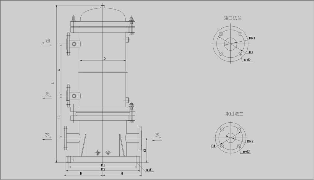
|
Model |
L |
C |
L1 |
Cl |
H |
D |
DI |
D2 |
D3 |
D4 |
DN1 | DN2 |
n-dl |
n-d2 |
n・d3 |
Flow of oil (L/min) |
Weight (kg) |
| GLL3-4L | 1220 | 682 |
100 |
32 |
75 |
125 |
|||||||||||
| GLL3-5L | 1520 | 982 | 320 | 100 | 190 | 219 | 320 | 360 | 100 |
32 |
8-Φ24 |
4-Φ17.5 | 4-Φ17.5 | 100 |
140 |
||
| GLL3-6L | 1820 | 1282 |
110 |
40 | 125 |
155 |
|||||||||||
| GLL3-7L | 2050 | 1512 | 150 |
165 |
|||||||||||||
| GLL4-12L | 1630 | 960 | 250 |
268 |
|||||||||||||
| GLL4-16L | 2035 | 1365 |
145 |
65 | 4-Φ17.5 | 350 |
330 |
||||||||||
| GLL4-20L | 2445 | 1775 | 400 | 130 | 262 | 325 | 440 | 480 | 145 |
65 |
8-Φ24 |
4-Φ17.5 | 450 |
390 |
|||
| GLL4-24L | 2845 | 2175 |
160 |
80 | 8-Φ17.5 | 550 |
485 |
||||||||||
| GLL4-28L | 3255 | 2585 | 650 |
566 |
|||||||||||||
| GLL5-35L | 2545 | 1692 |
180 |
100 | 625 |
605 |
|||||||||||
| GLL5-40L | 2815 | 1962 | 750 |
660 |
|||||||||||||
| GLL5-45L | 3065 | 2202 | 530 | 180 | 315 | 426 | 570 | 620 | 180 | 100 |
8-Φ28 |
8-Φ17.5 | 8-Φ17.5 | 875 |
781 |
||
| GLL5-50L | 3335 | 2472 |
210 |
125 | 1000 |
860 |
|||||||||||
| GLL5-60L | 3875 | 3012 | 1250 |
960 |
|||||||||||||
| GLL6-80L | 3170 | 2015 | 1500 | 1630 | |||||||||||||
|
GLL6-100L |
3770 | 2615 | 690 | 215 | 500 | 616 | 800 | 870 |
295 |
295 | 200 | 200 |
8-Φ35 |
8-Φ22 |
8-Φ22 |
2000 | 1900 |
|
GLL6-120L |
4370 | 3215 | 2500 | 2175 |
1. Calculation method
(1) Required heat transfer area A(m2)
QA=Arm -K
⑵Amount of heat:Q(Kca l/h)
Q=(H-T2)CW=(t2-tl)C,W, <2=Amount of heat(kca l/h) k=Heat transfer coefficient(kca l/m2h°C) Atiii =Mean temperature difference(°C)
Among them:D 1= inlet oil temperature °C 2=Export of oil temperature°C 。=Import water temperature°C
2=Export water temperature°C C=The specific heat of oil(kca l/kg。。 The specific heat of water(kca l/kg°C)
W=The flow of oil(kg/h) '=The flow of water(kg/h)
(3)Average temperature difference left T m(°C)
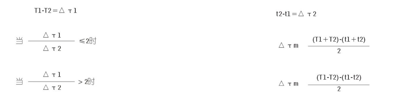
(4)Heat transfer coefficient:K(kca l/m2h°C)
a)When the cooling water flow is small and the working oil viscosity is high, K = 200 is taken;
b)Generally take K=250 when working oil;
c)When the cooling water flow is large and the working oil viscosity is low, K = 350~400 is taken0;
2. Estimation
|
Motor power KW |
7.5-10 |
10-15 |
15-20 |
20-30 |
30-40 |
40-75 |
75-100 |
100-120 |
120-150 |
150-200 |
| Selected cooling area(nf) |
0.4 0.6 |
0.8 1.0 |
1.2 1.3 |
1.7 2.1 |
2.6 3 |
3.5 4 |
5 6 |
7 8 |
8 9 |
10 11 |