Lksi Level Control Indicator Series
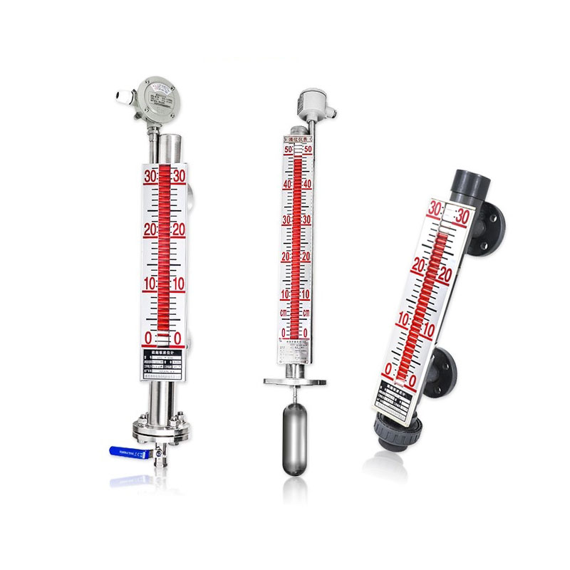
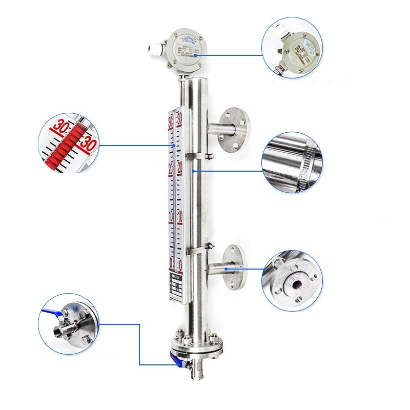
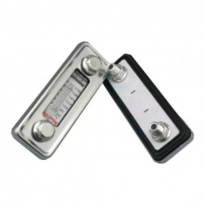
LKSI level control indicator is an advanced visual and electronic control device that can be used for monitoring level of the oil in an open or closed container. It is composed of a stainless steel bowl, magnetic bobbers inside bowl, magnetic plate indicator outside bowl and a relay for controlling fluid level.
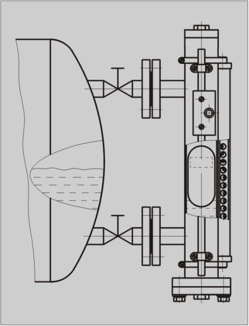
When the liquid in the container passes the lower connect pipe of liquid level control indicator body, the liquid enters into stainless steel pipe to make the magnetic float in the pipe begin to lift, the magnetic wing out of the pipe turns under the function of the magnetic force of the float,the w- ing turns from the green to the red, that means the juncture of green color and red color of mag netic wing is the liquid level in the container. If the liquid level of the container needs three control points, three control relays can be fixed at the corresponding liquid level control heights, when the liquid level rises or descends to the control point, the control relay is cutoff or put through under the function of the magnetic force of the float to make the alarm work or the oil pump motor start or stop to control the liquid level position. If the relay contact touches the alarm, it also can be us ed for liquid level alarm indicator.
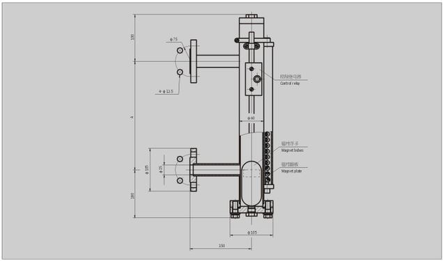
Distance of two flanges A:
Number of control points:1、2、3……
Omit if use hydraulic oil
BH:water-glycol
oltage: 24V或or 220V
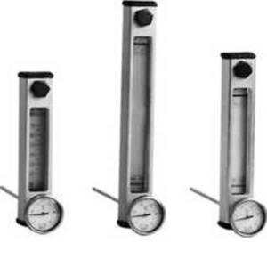
Level control indicator
Note: 1. Minimum spacing between liquid level control points is 90mm.
Standard A is 600, 800, 1000, 1200, 1500, 1800mm
2. The distance between the two connecting flanges has special requirements, please call or write to us
(1)12V 24V 36VDC
1. Tenip(°C): -20 — 100
2. Time of motion(ms): 1.7
3. Contact resistance(Q): 0.15
4. Contact capacity: DC24(V) x 0.2(A)
5. Life: 106
(2)110V 220VAC
1. Temp (°C): -20 — 100
2. Time of motion(ms): 1.7
3. Contact resistance(Q): 0.2
4. Contact capacity: AC220; 110(V) x 0.2(A)
5. Life: 106

a. Close the valves of the upper and lower connect pipes;
I). The process to absorl) the articles and release the liquid in steel pipe fully;
c. Open the lower flange cover;
(I. Take out the float and clean the articles al)sorl)e(l out of the float;
e. Pay attention to the up a nd-down direction of the float when reassemble the f- loat to avoid the error indication and wrong alarm of the indicator and control relay.
Strong magnetic field is prohibited near the magnetic wing indicator when u- sing in order to prevent from interfering the normal work of the wing.