Wholesale Price Return Vent Filter Sizes - Zu—h Qu-h High Pressure Line Filter Series – Xinyuan
Wholesale Price Return Vent Filter Sizes - Zu—h Qu-h High Pressure Line Filter Series – Xinyuan Detail:
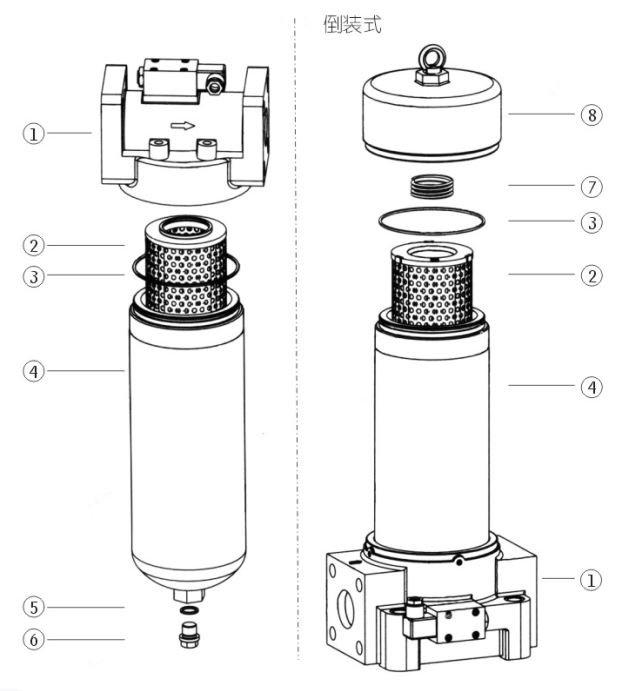
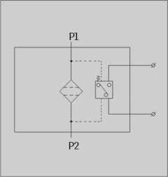
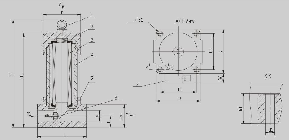
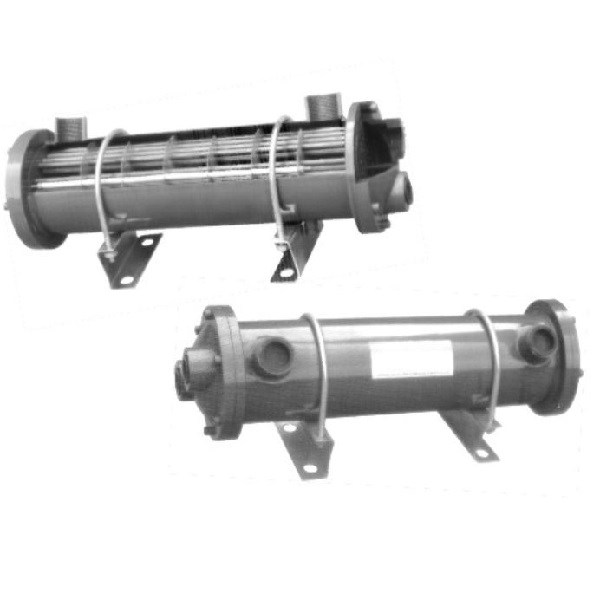
The superheater is installed on the pressure line of the hydraulic system to drop off the resin, pitch, carbon residue, etc. from the mechanical impurities and the chemical reaction of the hydraulic oil itself, thus prevent it spool stuck, throttle small hole gap and damping hole plug and hydraulic components too fast wear, and other failures. The filter has good filtering effect and high precision, but it is difficult to clean after being blocked, and the temperature core must be replaced. The leakage device is equipped with a pressure difference sending device. When the leakage core is blocked to the pressure difference of the oil inlet and outlet is 0.35 MPA, the switch signal is sent out, and the temperature core is replaced at this time to achieve the goal of protecting the system safety. The over-temperature precision is calibrated with absolute over-temperature precision and over-drop ratio of 03,5,10,20 & GT 200, overtemperature efficiency i1n99.5% , in accordance with ISO standard.
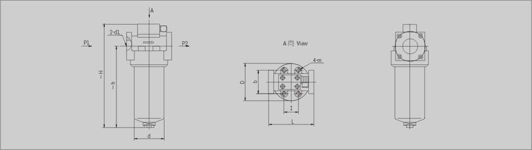
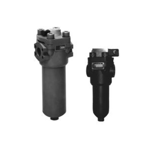
ZU-Hx QU-H series filters are of high pressure type and used in the pressure line of hydraulic system. Filter element is made of glass fibre or paper. Differential pressure indicator signals when the pressure drop across filter element reaches 0.35MPa.
|
Number |
Name |
Note |
|
1 |
Fliter head | |
|
2 |
Element |
Wearing parts |
|
3 |
O-ring |
Wearing parts |
|
4 |
Housing | |
|
5 |
O-ring |
Wearing parts |
|
6 |
Screw | |
|
7 |
Spring | |
|
8 |
Cap |
ZU:Paper filter
QU:Fib re filter
WU:Wire mesh filter
I :With by-pass valve
Omit if use without by-pass valve
BH:Water-glycol
Omit if use hydraulic oil
Pressure class: H: 32MPa
E: W22MPa
P:With CMS indicator
Omit if without indicator
Omit if threaded connection
F: flanged connection
B:plated connection
DL: inverted threaded connection
DF: inverted flanged connection
DFA:inverted flanged connection A
DFB: inverted flanged connection B
BD: inverted plated connection
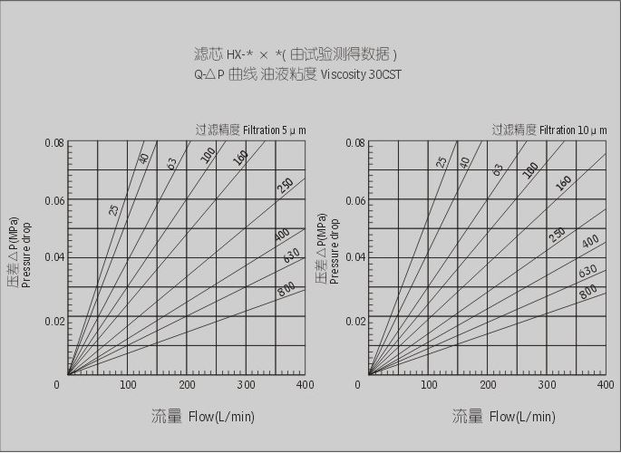
Filtration accuracy (p m)
Flow rate (L/min)
|
Model |
Dia. (mm) |
Flow rate (L/min) |
Filtr. (U ni) |
Press. (MPa) |
Pressure loss(MPa) |
Indicator power |
Weight (Kg) |
Model of element |
Connect |
|
|
Initial |
Max. |
|||||||||
| 匕 U-H10x*P | 15 |
10 |
1 3 5 10 20 30 |
32 |
0.08 |
0.35 |
24V/48W 220V/50W |
3.6 | HX – 10 x * # |
Threaded |
| n U-H25x*P |
25 |
5.0 | HX – 25 x * # | |||||||
| q U-H40x*P | 20 |
40 |
0.1 |
8.0 | HX-40x*# | |||||
| % U-H63x*P |
63 |
9.8 | HX – 63 x * # | |||||||
| q U-H100x*P | 25 |
100 |
12.0 |
HX – 100 x * # | ||||||
| 匕 U-H160x*P | 32 |
160 |
0.12 |
18.2 |
HX – 160 x * # | |||||
| n U-H250x*FP | 40 |
250 |
23.0 |
HX – 250 x * # |
Flanged |
|||||
| q U-H400x*FP | 50 |
400 |
0.15 |
33.8 |
HX-400X*# | |||||
| % U-H630x*FP | 53 |
630 |
42.0 |
HX – 630 x * # | ||||||
| * U-H800x*FP |
800 |
52.0 |
HX – 800 x * # | |||||||
Note: * is represents filtration, # is filter media If the filter flu id is water-glycol, usage pressure 32MPa,flower rate 63L/min,filter media is paper, the filter equipped with indic ator and by-pass valve, the model of the fi-lter is ZUI • BH 一 H63 x *P. That of the element is HX • BH – H63 x * if filter media is fib re and the filter equipped with indica tor, the model of the filter is QU • BH – H63 x 夫 P, that of the element is HX • BH- H63 x *Q;if filter media is wire mesh and the filter equipped with indicator, the model of the filter is WU • BH – H63 x 大P,That of the element is HX • BH- H63 x *W;
|
Model |
Dia. (mm) |
Flow rate (L/min) |
Filtr. (H m) |
Press. (Mpa) |
Pressure loss(MPa) |
Indicator power |
Weight (Kg) |
Model of element |
Connect |
|
|
Initial |
Max. |
|||||||||
|
I U-H10x*BP |
15 | 10 | 1
3 5 10 20 30 40 |
32 |
0.08 |
0.35 |
24V/48W 220V/50W |
5.7 |
HBX -10x* | Plated |
|
I U-H25x*BP |
25 |
7.0 |
HBX 一 25 x 大 | |||||||
|
I U-H40x*BP |
25 | 40 |
0.1 |
11.5 |
HBX-40X* | |||||
|
% U-H63x*BP |
63 |
13.2 |
HBX 一 63 x 大 | |||||||
|
% U-H100x*BP |
25 | 100 |
15.0 |
HBX – 110 x * | ||||||
|
% U-H160x*BP |
32 | 160 |
0.12 |
21.4 |
HBX – 160 x * | |||||
|
% U-H250x*BP |
40 | 250 |
25.7 |
HBX – 250 x * | ||||||
|
% U-H400x*BP |
50 | 400 |
0.15 |
38.0 |
HBX – 400 x* | |||||
|
% U-H630x*BP |
630 |
42.3 |
HBX – 630 x * | |||||||
|
% U-H10x*DLP |
15 | 10 |
0.08 |
8.5 |
HDX-lOx* | Inverted
threaded |
||||
|
赤 U-H25x*DLP |
25 |
9.9 |
HDX-25X* | |||||||
|
赤 U-H40x*DLP |
20 | 40 |
0.1 |
16.4 |
HDX-40X* | |||||
|
&U-H63x*DLP |
63 |
18.9 |
HDX-63X* | |||||||
|
^U-H100x*DLP |
25 | 100 |
22.5 |
HDX-lOOx* | ||||||
|
&U-H160x*DLP |
32 | 160 |
0.15 |
33.4 |
HDX-160X* | |||||
|
&U-H10x*DFP |
15 | 10 |
0.08 |
8.6 |
HDX-lOx* | Inverted flanged | ||||
|
&U-H25x*DFP |
25 |
10.0 |
HDX-25X* | |||||||
|
&U-H40x*DFP |
20 | 40 |
0.1 |
16.6 |
HDX-40X* | |||||
|
&U-H63x*DFP |
63 |
19.2 |
HDX-63X* | |||||||
|
^U-H100x*DFP |
25 | 100 | 22.9 | HDX – 100 x * | ||||||
|
&U-H160x*DFP |
32 | 160 |
0.12 |
34.0 |
HDX-160X* | |||||
|
<U-H250x*DFP |
40 | 250 |
41.9 |
HDX – 250 x* | ||||||
|
<U-H400x*DFP |
50 | 400 |
0.15 |
57.6 |
HDX – 400 x* | |||||
|
%U-H630x*DFP |
53 | 630 |
62.4 |
HDX – 630 x* | ||||||
|
&U-H800 x*DFP |
800 | HDX – 800 x* | ||||||||
|
% U-H10x*DFAP |
15 | 10 |
0.08 |
8.6 |
HDX-lOx* | Inverted
flanged A |
||||
|
% U-H25x*DFAP |
25 |
10.0 |
HDX-25X* | |||||||
|
% U-H40x*DFAP |
20 | 40 |
16.6 |
HDX-40X* | ||||||
|
% U-H63x*DFAP |
63 |
0.1 |
19.2 |
HDX-63X* | ||||||
|
% U-H100 x *DFAP |
25 | 100 |
22.9 |
HDX -100 x* | ||||||
|
% U-H160 x *DFAP |
32 | 160 |
0.12 |
34.0 |
HDX -160 x* | |||||
|
% U-H250 x *DFAP |
40 | 250 |
41.9 |
HDX – 250 x* | ||||||
|
% U-H400 x *DFAP |
50 | 400 |
0.15 |
57.6 |
HDX – 400 x* | |||||
|
* U-H630 x *DFAP |
53 | 630 |
62.4 |
HDX – 630 x* | ||||||
|
* U-H800 x *DFAP |
800 | HDX – 800 x* | ||||||||
|
* U-H10x*DFBP |
15 | 10 |
0.08 |
8.6 |
HDX-lOx* | Inverted
flanged B |
||||
|
* U-H25x*DFBP |
25 |
10.0 |
HDX-25X* | |||||||
|
* U-H40x*DFBP |
20 | 40 |
16.6 |
HDX-40X* | ||||||
|
* U-H63x*DFBP |
63 |
0.1 |
19.2 |
HDX-63X* | ||||||
|
* U-H1OO x *DFBP |
25 | 100 |
22.9 |
HDX -100 x* | ||||||
|
% U-H160x*DFBP |
32 | 160 |
0.12 |
34.0 |
HDX -160 x* | |||||
|
* U-H250 x *DFBP |
40 | 250 |
41.9 |
HDX – 250 x* | ||||||
|
% U-H400 x*DFBP |
50 | 400 |
0.15 |
57.6 |
HDX – 400 x* | |||||
|
% U-H630 x *DFBP |
53 | 630 |
62.4 |
HDX – 630 x* | ||||||
|
% U-H800x*DFBP |
800 | HDX – 800 x* | ||||||||
|
* U-H10x*BDP |
15 | 10 |
0.08 |
8.4 |
HDX-lOx* |
Inverted plate |
||||
|
* U-H25x*BDP |
25 |
9.8 |
HDX-25X* | |||||||
|
* U-H40x*BDP |
20 | 40 |
0.1 |
16.3 |
HDX-40X* | |||||
|
* U-H63x*BDP |
63 |
18.9 |
HDX-63X* | |||||||
|
* U-H1OO x *BDP |
25 | 100 |
22.5 |
HDX -100 x* | ||||||
|
% U-H160x*BDP |
40 | 160 |
0.12 |
33.6 |
HDX -160 x* | |||||
|
% U-H250 x *BDP |
250 |
41.3 |
HDX – 250 x* | |||||||
|
% U-H400 x *BDP |
50 | 400 |
0.15 |
57.0 |
HDX – 400 x* | |||||
|
% U-H630 x *BDP |
630 |
61.8 |
HDX – 630 x* | |||||||
|
* U-H800 x *BDP |
800 | HDX – 800 x* | ||||||||
1. Threaded connection
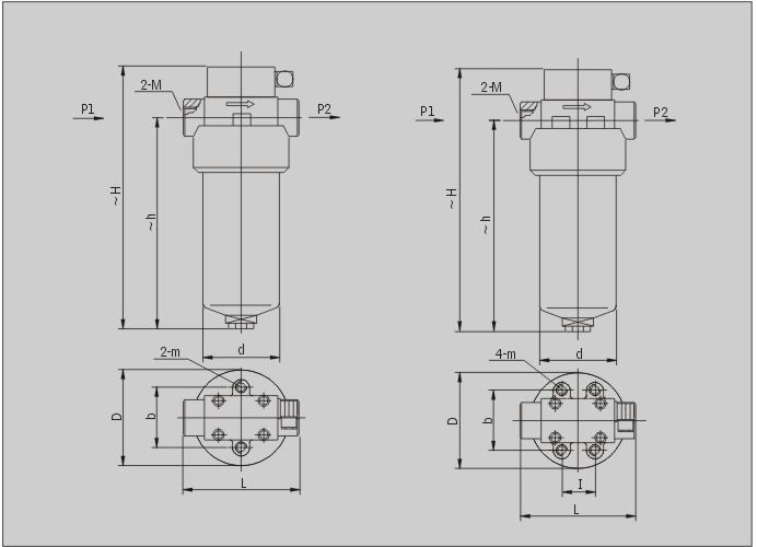
| Model | Size (mm) | ||||||||
| 〜H | ~h | L | I | 1) |
D |
(1 |
m |
M | |
| Zq U- H10x*P | 198 | 140 | 118 | 70 | Φ88 |
Φ73 |
2-M6 | M27 x 2 | |
| Zq U – H25x*P | 288 | 230 | |||||||
| Zq U – H40x*P | 255 | 194 | 128 | 44 | 86 | Φ124 | Φ102 | 4-M10 | M33 x 2 |
| Zq U – H63x*P | 323 | 262 | |||||||
| ZqU - H100x*P | 394 | 329 | M42x2 | ||||||
| ZqU - H160x*P | 435 | 362 | 166 | 60 | 100 | Φ146 | Φ121 | M48x2 | |
Note: 10L/min connecting thread M18 x 1.5, 25L/min connecting thread M22 x 1.5 is special order. The model will be ZUT-H10 x *P and ZUT-H25 x *P.
Change instructions
① The original flow rate of 10l/min is 10l/min, except the screw size of the oil inlet and outlet is changed from 2-M18XL5 to 2-M27x2(model Zu-h10x * P) , the other size is the same, 2-M18X1.5 is special, order, model is Zut10x * P, 2-M27 x 2(model ZU-H25 x * P) is changed from 2-M22 x l 5 to 2-M27 x 2(model ZU-H25 x * P) , the other size, unchanged, 2-M22 XL5 is a special order, model zut-h25 x * P, the above changes will take effect from January 1,1986.
② The CS-V differential pressure transmitter in the original sample has been changed from s to P and is a CMS differential pressure transmitter. The CMS differential pressure transmitter is based on the CS-V differential pressure transmitter, it is a more advanced and reliable anti-signal device with visual observation and electric transmission.
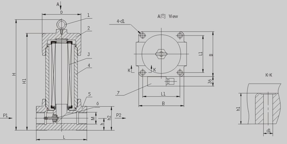
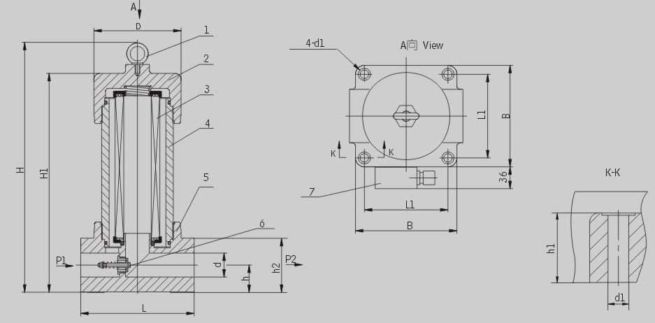
2. Flanged connection
| Model | Size (mm) | ||||||||
| 〜H | ~h | L | I | b | D | d |
D1 |
m |
|
| Zq U – H250x*FP | 508 | 430 | 166 | 60 | 100 | 146 | 121 | Φ40 | M10 |
| ZqU-H400x*FP | 545 | 461 | 206 | 123 | 170 | 146 | Φ50 | M12 | |
| ZQ|u-H630x*FP | 647 | 563 | 128 | Φ55 | |||||
| ZQU-H800x*FP | 767 | 683 | |||||||
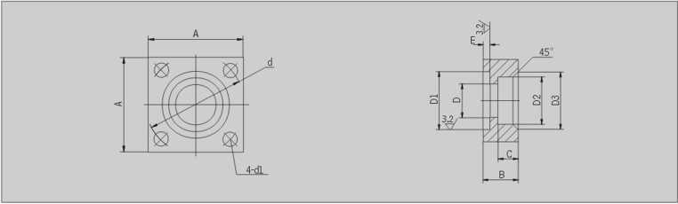
2.1 Manufacturing connecting flange as follow drawing
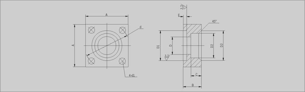
| Model | Size (mm) |
ring for flange |
Screw for flange |
||||||||||||
|
A |
B |
C |
D |
DI |
D2 |
D3 |
d |
E |
D1 | ||||||
|
q U – H250x*FP |
100 | 30 |
18 |
Φ40 | Φ55 |
0 -0.2 |
Φ52 | + 0.2
0 |
Φ60 |
Φ98 |
2.4 |
0 -0.1 |
17 | Φ55 x 3.1 | M16 x 45 |
|
q U- H400 x *FP |
123 | 36 |
20 |
Φ52 | Φ73 | Φ65 | Φ73 | Φ118 |
4.5 |
22 | Φ73 x 5.7 | M20 x 60 | |||
|
q U- H630 x *FP |
142 | 42 |
22 |
Φ55 | Φ77 | Φ)77 | Φ85 | Φ145 | Φ80 x 5.7 | M20 x 65 | |||||
|
q U- H800 x *FP |
142 | 42 |
22 |
Φ55 | Φ77 | Φ77 | Φ85 | Φ14545 | Φ)80 x 5.7 | M20 x 65 | |||||
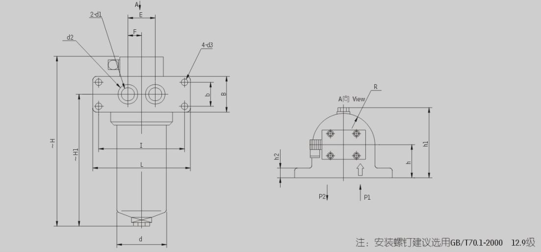
3. Plated connection
|
Model |
Size (mm) | |||||||||||||||
|
〜H |
~H1 |
R |
(1 |
L |
B |
I |
b |
E |
F |
h |
hl |
h2 |
(11 |
d2 |
(13 |
|
| Zq U – H10x*BP | 210 |
142 |
46 |
Φ73 |
158 | 60 | 128 | 30 | 40 |
20 |
50 | 110 | 22 | Φ15 | Φ24 | Φ13 |
| Zq U – H25x*BP | 300 |
232 |
||||||||||||||
| Zq U-H40x*BP | 269 |
109 |
62 | Φ102 | 190 | 64 | 160 | 32 | 50 |
25 |
65 | 138 | 25 | Φ25 | Φ32 | Φ15 |
| Zq U – H63x*BP | 337 |
267 |
||||||||||||||
| Zq U-H100x*BP | 399 |
329 |
||||||||||||||
| Zq U – H160x*BP | 426 |
353 |
73 | Φ121 | 212 | 72 | 180 |
40 |
60 |
30 |
77 | 164 | 30 | Φ32 | Φ40 | Φ17 |
| Zq U – H250x*BP | 507 |
429 |
80 |
48 |
Φ40 | Φ50 | ||||||||||
| Zq U-H400 x*BP | 554 |
461 |
85 | Φ146 | 275 |
110 |
225 | 60 | 80 |
40 |
92 | 194 |
40 |
Φ50 | Φ65 | Φ26 |
| Zq U – H630x*BP | 654 |
561 |
||||||||||||||
4. Inverted threaded connection
1. Screw
2. Cover
3. Element
4. Bowl
5. Filter head
6. By-pass valve
7. Indicator
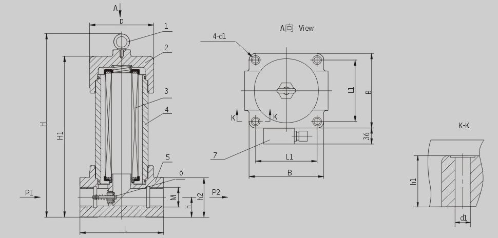
| Model |
Size (mm) |
||||||||||
|
H |
Hl |
L |
LI |
B |
(11 |
h |
hl |
112 |
M |
D |
|
| ZQU- H10x*DLP | 198 | 148 |
130 |
95 |
115 |
Φ19 |
27.5 |
33 |
54 | M27x2 |
Φ92 |
| ZQU-H25x*DLP | 288 | 238 | |||||||||
| ZQU-H40x*DLP | 247 | 197 |
156 |
115 |
145 |
Φ14 |
34 |
41 |
68 | M33x2 | Φ124 |
| ZQU-H63x*DLP | 315 | 265 | |||||||||
| ZQU- H100x*DLP | 377 | 327 | M42 x 2 | ||||||||
| ZQU- H160x*DLP | 415 | 365 |
190 |
140 |
170 |
46 |
50 |
92 | M48 x 2 | Φ146 | |
5. Inverted flange connection
1. Screw
2. Cover
3. Element
4. Bowl
5. Filter head
6. By-pass valve
7. Indicator
|
Model |
Size (mm) |
||||||||||
|
H |
Hl |
D |
L |
LL |
B |
D1 |
h |
hl | h2 |
d |
|
| ZQU- H10x*DFP | 198 | 148 |
Φ92 |
130 |
95 |
115 | Φ9 |
27.5 |
33 | 54 |
Φ18 |
| ZQU-H25x*DFP | 288 | 238 | |||||||||
| ZQU-H40x*DFP | 247 | 197 | Φ124 | 156 |
115 |
145 |
Φ14 |
34 |
41 |
68 |
Φ25 |
| ZQU-H63x*DFP | 315 | 265 | |||||||||
| ZQU- H100x*DFP | 377 | 327 | |||||||||
| ZQU- H160x*DFP | 415 | 365 | Φ146 | 190 |
140 |
170 |
46 |
50 | 92 |
Φ32 |
|
| ZQU-H250x*DFP | 485 | 435 |
Φ40 |
||||||||
| ZQU-H400x*DFP | 532 | 482 | Φ176 | 240 |
160 |
200 |
Φ18 |
63 | 75 |
122 |
Φ50 |
| ZQU-H630x*DFP | 632 | 582 | Φ55 | ||||||||
| ZQU-H800x*DFP | 752 | 702 | |||||||||
Note: the sizes of flange see page 72
6. Inverted flanged connection A
1. Screw
2. Cover
3. Element
4. Bowl
5. Filter head
6. By-pass valve
7. Indicator
|
Model |
Size (mm) |
|||||||||||
|
H |
Hl |
L |
LI |
L2 |
B |
D1 |
h |
hl |
h2 |
d | D | |
|
ZQU-H10 x * DFAP |
198 | 148 |
122.5 |
65 |
95 |
115 | Φ9 |
27.5 |
33 |
54 |
Φ18 |
Φ92 |
|
ZQU-H25X* DFAP |
288 | 238 | ||||||||||
|
ZQU-H40 x * DFAP |
247 | 197 |
150.5 |
78 |
115 |
145 | Φ14 |
34 |
41 |
68 |
Φ25 | Φ124 |
|
ZQU-H63 x* DFAP |
315 | 265 | ||||||||||
| ZQ U-HlOOx* DFAP | 377 | 327 | ||||||||||
| ZQ U-H160 x * DFAP | 415 | 365 |
180 |
95 |
140 |
170 |
46 |
50 |
92 |
Φ32 | Φ146 | |
| ZQU-H250 x * DFAP | 485 | 435 | Φ40 | |||||||||
| ZQ U-H400 x * DFAP | 532 | 482 |
220 |
120 |
160 |
200 |
Φ18 |
63 |
75 |
122 |
Φ50 | Φ176 |
| ZQU-H630 x * DFAP | 632 | 582 | Φ55 | |||||||||
| ZQU-H800 x * DFAP | 752 | 702 | ||||||||||
Note:the sizes of flange see page 72
7. Inverted flanged connection B
1. Screw
2. Cover
3. Element
4. Bowl
5. Filter head
6. By-pass valve
7. Indicator
| ZQ U-H10 x * DFBP | 198 | 148 |
122.5 |
65 |
95 |
115 | Φ9 |
27.5 |
33 |
54 |
Φ18 | Φ92 |
| ZQ U-H25 x * DFBP | 288 | 238 | ||||||||||
| ZQ U-H40X* DFBP | 247 | 197 |
150.5 |
78 |
115 |
145 | Φ14 |
34 |
41 |
68 |
Φ25 | Φ24 |
| ZQ U-H63 x * DFBP | 315 | 265 | ||||||||||
| ZQU-HlOOx* DFBP | 377 | 327 | ||||||||||
| ZQ U-H160 x * DFBP | 415 | 365 |
180 |
95 |
140 |
170 |
46 |
50 |
92 |
Φ32 | Φ146 | |
| ZQ U-H250 x * DFBP | 485 | 435 | Φ40 | |||||||||
| ZQ U-H400 x * DFBP | 532 | 482 |
220 |
120 |
160 |
200 |
Φ18 |
63 |
75 |
122 |
Φ50 | Φ176 |
| ZQ U-H630 x * DFBP | 632 | 582 | Φ55 | |||||||||
| ZQ U-H800 x * DFBP | 752 | 702 |
Note:the sizes of flange see page 72
8. Inverted plated connection
1. Screw
2. Cover
3. Element
4. Bowl
5. Filter head
6. By-pass valve
7. Indicator

| Model |
Size (mm) |
||||||||||||
|
H |
Hl |
D |
L |
Ll |
B |
d1 |
E |
hl | h2 |
d3 |
d4 |
b |
|
| ZQ U-H10 x * BDP | 196 | 146 |
Φ92 |
130 |
90 |
115 |
Φ11.5 |
60 |
31 | 50 | Φ15 | Φ24 | 14 |
| ZQU-H25 x * BDP | 286 | 236 | |||||||||||
| ZQU-H40 x * BDP | 245 | 195 | Φ124 | 156 |
115 |
145 |
Φ16 |
88 |
39 | 64 | Φ25 | Φ38 | 15 |
| ZQ U-H63 x * BDP | 313 | 263 | |||||||||||
| ZQ U-H100 x * BDP | 375 | 325 | |||||||||||
| ZQ U-H160X* BDP | 413 | 363 | Φ146 | 190 |
135 |
170 |
Φ18 |
104 |
48 | 88 | Φ40 | Φ50 | 23 |
| ZQ U-H250 x * BDP | 483 | 433 | |||||||||||
| ZQ U-H400 x * BDP | 530 | 480 | Φ176 | 240 |
160 |
200 |
Φ26 |
144 |
70 |
118 |
Φ50 | Φ65 | 24 |
| ZQ U-H630 x * BDP | 630 | 580 | |||||||||||
| ZQ U-H800 x * BDP | 750 | 700 | |||||||||||
9. Connecting flange as follow drawing
1. Screw
2. Cover
3. Element
4. Bowl
5. Filter head
6. By-pass valve
7. Indicator
| Model |
Size (mm) |
”0″ring for flange |
Screw for flange |
||||||||||||
|
A |
B |
C |
D |
DI |
D2 |
D3 |
D |
E |
dl | ||||||
| ZQU-H10x*DAP |
52 |
22 |
11 | Φ18 | Φ30 |
0 -0.2 |
Φ28 |
+ 0.2 0 |
Φ36 | Φ50 | 2.4 |
0 -0.1 |
Φ9 | Φ30 x 3.1 |
M 8 x 40 |
| ZQ U-H25x*DAP | |||||||||||||||
| ZQ U-H40x*DAP |
66 |
12 | Φ25 | Φ40 |
Φ35 |
Φ43 | Φ62 | Φ11 | Φ40×3.1 | M 10 x 45 | |||||
| ZQ U-H63x*DAP | |||||||||||||||
| ZQU-H100x*DAP | |||||||||||||||
| ZQ U-H160x*DAP |
90 |
26 |
16 | Φ32 | Φ50 |
Φ43 |
Φ51 | Φ85 | Φ17 | Φ50 x 3.1 | M 16 x 45 | ||||
| ZQU-H250x*DAP | Φ40 |
Φ52 |
Φ60 | ||||||||||||
| ZQU-H400x*DAP |
120 |
36 |
20 | Φ52 | Φ73 | Φ65 | Φ73 | Φ118 | 4.5 | Φ22 | Φ73 x 5.7 | M 20 x 65 | |||
| ZQ U-H630x*DAP | Φ55 | Φ80 | Φ77 | Φ85 | Φ 80 x 5.7 | ||||||||||
| ZQU-H800x*DAP | |||||||||||||||
Note: :△为F, FA, FBO Note: △ is F, FA,FB
Product detail pictures:
Related Product Guide:
We now have a highly efficient crew to deal with inquiries from clients. Our intention is "100% shopper pleasure by our merchandise quality, price tag & our staff service" and take pleasure in a very good standing amongst purchasers. With quite a few factories, we can easily provide a wide vary of Wholesale Price Return Vent Filter Sizes - Zu—h Qu-h High Pressure Line Filter Series – Xinyuan , The product will supply to all over the world, such as: Costa Rica, Kuwait, Belize, We've a good reputation for stable quality solutions, well received by customers at home and abroad. Our company would be guided by the idea of "Standing in Domestic Markets, Walking into International Markets". We sincerely hope that we could do business with customers both at home and abroad. We expect sincere cooperation and common development!
Sales manager is very enthusiastic and professional, gave us a great concessions and product quality is very good,thank you very much!
Products categories
-
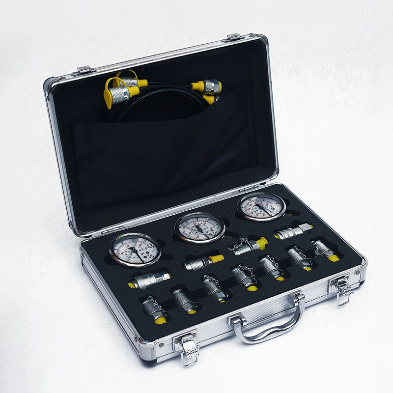
OEM/ODM China Hydraulic Test Point - Test Kit ...
-
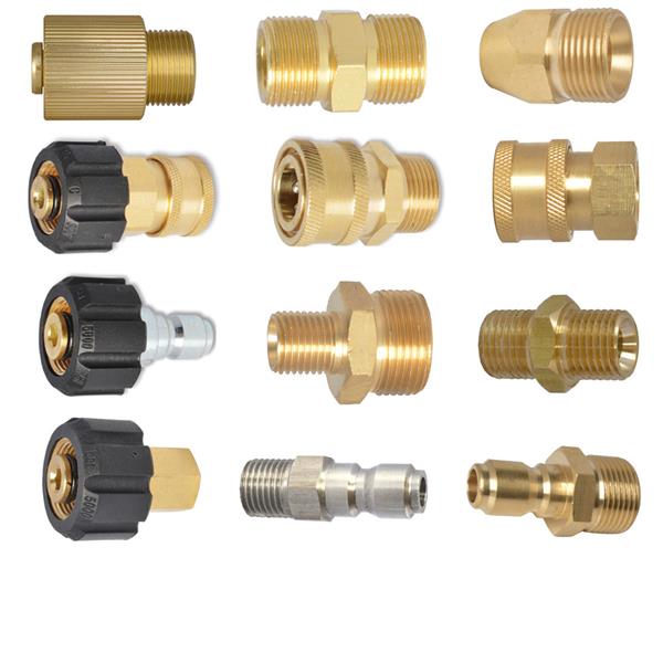
2021 Good Quality Pok Foam Nozzle - Adapter &a...
-
Reasonable price for Gas Tank Monitor - KF Pre...
-
Chinese Professional Tank Level Indicator - OR...
-
Ordinary Discount Petrol Level Indicator - Hig...
-
Wholesale Dealers of Return Air Register With F...


